PID Controller
Simulation companion to flight-controller — 6-DOF quadcopter physics, cascaded PID with anti-windup, 3D visualisation.
GitHub repo: PID Controller
Last update: 2026/06/11
From altitude PID to 4-axis cascade
This started as a single PID controlling vertical altitude — one DOF, gravity as the only disturbance. Over the past few weeks it has grown into a full 4-axis flight controller: cascaded angle→rate loops for roll and pitch, single-loop rate control for yaw, single-loop position control for altitude, motor mixing, NED physics, and a 3D visualisation. The codebase is structured to drop directly onto an ESP32 when the time comes for hardware.
This post walks through the architecture, the physics, the control structure, and the design decisions that mattered. It’s less a tutorial and more a record of what I learned by getting each piece wrong before getting it right.
Architecture
The system is five C modules and a Python visualiser. Each module has a single job and a narrow interface; they communicate through plain data types, never through shared state.
quad.c     → physics: forces in, motion out
mixer.c    → command translation: (thrust, roll, pitch, yaw) → 4 motor thrusts
pid.c      → generic single-axis PID with anti-windup
control.c  → cascade wiring: 6 PIDs composed into the full controller
main.c     → orchestration: the loop, the logging, the test scenarios
vis3d.py   → 3D visualisation, reads the CSV log
The pipeline for one simulation tick:
Setpoints → control_update → ControlOutput → mixer_compute → [F1..F4] → quad_step → QuadState'Each arrow is a narrow data handoff. The modules don’t know about each other’s internals. This is what makes the controller portable: quad.c is the simulated drone today and will be sensor reads + ESC writes tomorrow. Everything above it stays unchanged.
The physics: NED
The simulation lives in NED coordinates: x forward, y right, z down. This is the standard aerospace convention used by PX4, ArduPilot, MAVLink — every serious autopilot stack uses it, so committing to NED early means less translation work when I move to hardware.
NED feels backward at first (“down is positive?”), but the reasons are good:
- Compass headings match: positive yaw rotates the nose clockwise viewed from above, matching 0=N, 90=E, 180=S.
- Positive pitch = nose up: pull back on the stick, angle goes up.
- Positive roll = right wing down: bank right, angle is positive.
All three Euler angle signs match a pilot’s intuition only when z points down. Flip z to up (ENU), and two of the three reverse. The visualisation converts NED→ENU at the data-read step so matplotlib’s z-up view stays intuitive, but the sim itself stays in NED throughout.
The translational dynamics in quad.c look like this, after rotating body-frame thrust into the world frame:
float Fx_world = -F_total * (cr*sp*cy + sr*sy);
float Fy_world = -F_total * (cr*sp*sy - sr*cy);
float Fz_world = -F_total * (cr*cp);

float ax = Fx_world / MASS;
float ay = Fy_world / MASS;
float az = Fz_world / MASS + GRAVITY;   // gravity is +z in NED
The body thrust vector is (0, 0, -F_total) because thrust pushes “up” in body frame, and “up” is -z when z is down. Gravity is added to az because gravity pulls towards +z (down).
For rotational dynamics, with the inertia tensor diagonal and , the equations decouple:
Torques come from differential thrust and propeller reaction torque:
tau_roll  = L_EFF * (F[1] + F[2] - F[0] - F[3]);     // left - right
tau_pitch = L_EFF * (F[0] + F[2] - F[1] - F[3]);     // front - rear
tau_yaw   = YAW_TORQUE_RATIO * (F[0] + F[1] - F[2] - F[3]);  // CCW - CW
A subtle gotcha I burned an hour on: for an X-frame, the moment arm for roll/pitch is not ARM_LENGTH — it’s ARM_LENGTH * sin(45°), because the motors sit at 45° off the body x/y axes. Forgetting this gives a error in everything downstream that silently invalidates your gains.
The cascade
For roll and pitch, the controller is a two-stage cascade: an outer PID converts angle error into desired body rate, and an inner PID converts rate error into a torque command. Yaw is rate-only (no outer loop). Altitude is single-loop.
altitude PID                     → thrust_cmd
roll_angle PID  → roll_rate PID  → roll_cmd
pitch_angle PID → pitch_rate PID → pitch_cmd
                  yaw_rate PID   → yaw_cmd
Why cascade for roll and pitch? Three reasons that I came to appreciate slowly:
The inner variable is what the disturbance hits first. Wind doesn’t change attitude directly — it applies a torque, which changes the body rate, which integrates into an angle change. The rate loop sees the disturbance one integration step earlier and fights it before it ever becomes a visible angle error.
Sensor bandwidth matches loop bandwidth. Gyros are clean, fast, and read body rates directly. Angle estimates come from sensor fusion (gyro + accelerometer through a complementary filter or EKF), which is slower and noisier. Cascade lets each loop run on the sensor it deserves.
The inner loop transforms the plant. Before tuning, the body is a double integrator (torque → rate → angle) — nasty to control. After tuning the inner rate loop, the system behaves like a near-perfect rate follower to the outer loop. The outer loop now sees a much easier plant and only needs a P gain.
This last point is the deepest one. Cascade isn’t just code organisation — it’s a way of manufacturing an easier control problem out of a harder one.
In code, the wiring is six lines per axis:
c->roll_angle.setpoint = sp->roll;
float desired_p = pid_update(&c->roll_angle, s->roll, dt);
c->roll_rate.setpoint = desired_p;
out.roll_cmd = pid_update(&c->roll_rate, s->p, dt);
The output of the outer PID becomes the setpoint of the inner PID. That’s the entire cascade pattern.
The PID itself
The generic PID lives in pid.c and knows nothing about drones — it’s a piece of maths that gets reused six times across the controller, with different gains and different physical meanings, but identical code:
float pid_update(PID_Controller* pid, float feedback, float dt) {
    float error = pid->setpoint - feedback;
    float integral_new = pid->integral + error * dt;
    float derivative = (feedback - pid->prev_feedback) / dt;

    float output = pid->kp * error
                 + pid->ki * integral_new
                 - pid->kd * derivative;

    // Anti-windup: freeze integral if saturated in the wind-up direction
    if (output > pid->output_max) {
        output = pid->output_max;
        if (error > 0.0f) integral_new = pid->integral;
    } else if (output < pid->output_min) {
        output = pid->output_min;
        if (error < 0.0f) integral_new = pid->integral;
    }

    pid->integral = integral_new;
    pid->prev_feedback = feedback;
    return output;
}
Three subtle points that took me a while to internalise:
Derivative on measurement, not error. In a cascade, the outer loop’s output is the inner loop’s setpoint, and that setpoint can step abruptly. If derivative were computed on error, every setpoint change would produce a huge derivative spike (the “derivative kick”). Computing it on the measurement makes setpoint changes produce zero derivative, which is the right behaviour.
Use the new integral in the output, not the stale one. An earlier version of my PID had a one-tick lag where the output used integral from before the current update. This silently halved the effective I-gain — I had to use enormous ki values to compensate. Fixing it required re-tuning the altitude loop from scratch.
Anti-windup by conditional integration. When the controller saturates, the integral keeps growing if you don’t stop it — and when the saturation ends, you get massive overshoot. The fix: freeze the integral in the direction that would deepen saturation, but still allow it to move in the recovery direction. Three lines of code, huge impact on real-world behaviour.
The earlier version of this PID tracked time internally and computed dt from timestamps, with hard clamps to catch missed ticks. For a cascade with potentially different loop rates, this caused problems — the clamping silently mangled dt for any loop running slower than the expected rate. The fix was to make dt an explicit parameter. The controller no longer knows what time it is, and the caller is responsible for passing a sensible dt. Cleaner, more reusable, and impossible to silently break.
The mixer
The mixer converts abstract control commands (thrust, roll, pitch, yaw) into per-motor thrusts in Newtons. It’s the only module besides the physics that knows the airframe geometry.
F[0] = t - roll_cmd + pitch_cmd + yaw_cmd;   // M1 FR CCW
F[1] = t + roll_cmd - pitch_cmd + yaw_cmd;   // M2 RL CCW
F[2] = t + roll_cmd + pitch_cmd - yaw_cmd;   // M3 FL CW
F[3] = t - roll_cmd - pitch_cmd - yaw_cmd;   // M4 RR CW
Reading each column: roll command boosts left motors, pitch boosts front, yaw boosts CCW pair. Two + and two - per axis. Sign-convention bugs love to hide here — getting the mixer wrong is the single most common cause of “drone won’t take off” or “drone takes off and flips immediately.” Tests covering each axis direction in isolation catch most of these before they leave the bench.
Testing
Every module has its own test executable. The tests live in tests/ and link against the modules without going through main.c:
tests/
├── test_helpers.h     (one macro for ASSERT_NEAR)
├── test_pid.c         (9 tests)
├── test_mixer.c       (6 tests)
└── test_quad.c        (8 tests, including integration with mixer)
The PID tests cover each term in isolation, both saturation directions, anti-windup freeze and recovery, derivative-on-measurement, and reset. The mixer tests cover hover, each axis direction, and both clamp directions. The quad tests cover hover, each axis torque (with hand-crafted motor thrusts to verify physics), and integration tests that drive the physics through the mixer to verify that both modules agree on sign conventions.
That last category — the integration tests — caught a real bug where my mixer’s “positive roll” disagreed with the quad’s “positive roll” because the rotation matrix was in ENU while the torques were in NED. The pure-module tests both passed; only when they were composed did the inconsistency show.
make test runs all 23 tests in about a second. Every commit ends with all of them green, and adding a new module starts with writing its tests.
Tuning
The tuning order matters. Inside-out, slowest dynamics last:
- Roll rate inner loop, in isolation (other axes locked at zero). Step the rate setpoint, watch the response, tune
kpuntil you see oscillation, back off ~30%, addkdto kill overshoot, then smallkifor steady-state. - Pitch rate — same structure as roll, just copy gains and adjust.
- Yaw rate — single loop, no outer.
- Roll/pitch angle outer loops. With the inner rate loops solid, the outer loops see an easy plant and almost always end up as pure P controllers.
- Altitude. Tune last because it depends on the attitude loops behaving — tilt-induced thrust loss couples them.
For the cascade, the inner loop must be meaningfully faster than the outer — rule of thumb is at least 5× bandwidth separation. Violate this and the loops fight each other. In sim both loops run at 200 Hz, but the tuning enforces the bandwidth separation through gain choice.
Visualisation
The 3D visualiser reads the CSV log produced by the sim and renders the drone in real-time with matplotlib’s 3D backend. Camera follows the drone, with a trail showing the trajectory, an X-frame with labelled motors, and a nose marker showing heading.
NED→ENU conversion happens once at the data-read step. Position y and z flip (NED y is right, ENU y is left; NED z is down, ENU z is up), and pitch and yaw angles flip with them (their rotation axes flip direction). Roll doesn’t flip — the roll axis is the same in both frames, and the rotation in the y-z plane works out to the same physical motion either way.
pos = np.column_stack([df["x"].values, -df["y"].values, -df["z"].values])
roll  =  df["roll"].values
pitch = -df["pitch"].values
yaw   = -df["yaw"].values
After this conversion, the standard ZYX rotation matrix renders correctly with no sign hacks scattered through the rendering code.
What transfers to hardware
The whole controller — pid.c, mixer.c, control.c — is plain C with no platform dependencies, no dynamic allocation, no exotic floating-point. It drops onto an ESP32 with FreeRTOS or bare metal and runs unchanged.
What doesn’t transfer:
- The tuning. Gains are tuned against the simulated plant, which has perfect state estimation and idealised motors. The real drone has different inertia, motor response curves, prop efficiencies, sensor noise, ESC latency, and battery sag. Gains will be re-tuned from scratch on hardware.
- The physics module.
quad.cis the simulated drone. On hardware, it’s replaced by sensor reads (IMU complementary filter or EKF for attitude estimation, barometer for altitude) and motor writes (PWM to ESCs). Everything above this layer stays identical.
The architecture transfers; the numbers don’t. This is the right shape: write the controller once, deploy it many places.
Next steps
The sim is done as a sim. The next phase is hardware:
- MPU-6050 + ESP32 sensor fusion (complementary filter for attitude estimation)
- Port
pid.c,mixer.c,control.cto the ESP32, motors-off bench test first - ESC calibration and motor response characterisation
- Tethered first hover, then untethered
- Eventually: position hold via optical flow or visual odometry, then autonomous waypoint navigation
The controller is ready. The hardware is what comes next.
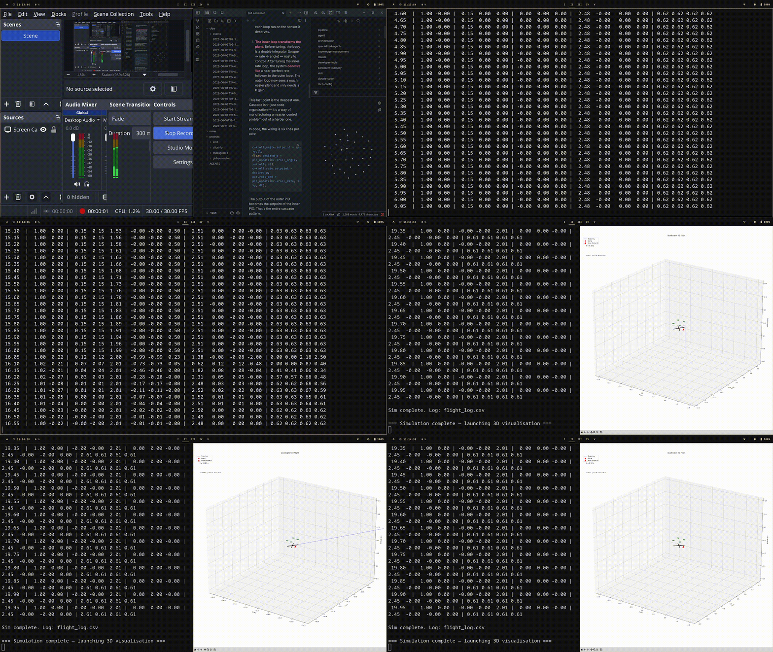
Demo
The flight scenario is 20 seconds, with these phases:
| Time | Command | What the drone does |
|---|---|---|
| 0–1 s | nothing | Sits on the ground at altitude 0, all angles zero |
| 1–4 s | altitude = 1 m | Climbs straight up to 1 m, settles |
| 4–8 s | roll = 0.15 rad (~8.6°) | Banks right while holding altitude |
| 8–12 s | pitch = 0.15 rad (~8.6°) | Pitches nose up while still banked, now tilted in both axes |
| 12–16 s | yaw_rate = 0.5 rad/s (~29°/s) | Rotates CW continuously for 4 seconds (~2 full turns), while still banked and pitched — a coordinated turn |
| 16–20 s | all commands back to zero | Returns to level hover at 1 m and stays there |